Category Archives: Coding

Netduino Plus 2 (NETMF) and WS2812 RGB LEDs

Some weeks ago I got some Adafruit NeoPixel, a compact RGB LED module. Each LED module has a WS2812 chip that only needs three wires: power, ground and data. The data protocol is self-clocking, at a rate of 800KHz. The LED modules can be chained to build longer LED stripes. (For more details see the Adafruit NeoPixel Überguide.)

Adafruit provides an Arduino library on github to control the LEDs, but there is no direct support for Microsoft .NET Microframework (NETMF) controllers like the Netduino Plus 2 that I was going to use.

Actually, there is an advanced guide to use NETMF controllers with the WS2812 LEDs, but it requires a custom firmware, because it seems that the GPIO pins of most NETMF controllers are not fast enough to switch the signal at the needed rate (there is a timing needed in the range of 0.4μs to 0.8μs and some websites found out that the GPIO pins have a latency of 17μs). As I nearly bricked a Netduino before, I didn’t want to dive into custom firmwares at this point.

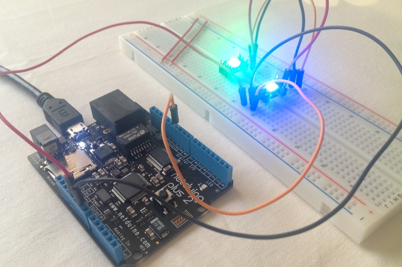
So I found a different way to send the control codes to the LEDs at the needed speed as the following photo proves:

Netduino with WS2812 LEDs

How does it work?

I thought that there must be a faster way to get signals off a Netduino Plus 2 because it has an Ethernet port and SD card slot, and I suppose they need to be adressed faster than 17μs (I haven’t evaluated this, so maybe I’m wrong with that, but it led me in the right direction). Looking at the ports that the Netduino provides my attention was drawn towards the SPI interface.

SPI (Serial Peripheral Interface) is a four-wire master-slave interface for full-duplex communication between chipsets. It has a clock wire (SCLK), output (MOSI) and input (MISO). Normally it can be used at a frequency up to some MHz, so the ports must be really fast.

My assumtion was, that I could only use the output (MOSI) pin, configure the frequency accordingly and send the needed control bytes on that wire to the LEDs. I tried some settings and data packets, but first without any success, but luckily I wasn’t the first one to try this, so I found some code snippets for different microcontrollers, that pointed me into the right direction, e.g. that a timing of 6.666MHz is recommended.

I’ve written two classes and uploaded them to github, so if you have a Netduino Plus 2 (or similar microcontroller) and don’t want to use a custom firmware to control WS2812 RGB LEDs, then maybe you want to give my code a try.

Code on github: https://github.com/jcoder/NetMFNeoPixelSPI

Usage example:

NeoPixelSPI neoPixel = new NeoPixelSPI(Pins.GPIO_PIN_D10, SPI.SPI_module.SPI1);
Pixel pixelRed = new Pixel(255, 0, 0);
Pixel pixelGreen = new Pixel(0, 255, 0);
Pixel pixelBlue = new Pixel(0, 0, 255);
Pixel pixelWhite = new Pixel(255, 255, 255);
Pixel[] block1 = new Pixel[] { pixelRed, pixelWhite };
Pixel[] block2 = new Pixel[] { pixelBlue, pixelGreen };
int waittime = 1000;
while (true)
{
 neoPixel.ShowPixels(block1);
 Thread.Sleep(waittime);
 neoPixel.ShowPixels(block2);
 Thread.Sleep(waittime);
}

The library code is not optimized (yet), and I didn’t write a helper class for easier handling of long LED stripes (because I don’t own one), so feel free to extend the code. I’m not quite sure if this approach is really a good one, but it worked for me.

Also feel free to leave a comment below if you have any remarks, ideas, etc.

As always: use this information and the code on your own risk. ;)

More Raspberry Pi Awesomeness: GPIO & Java

I’ve been playing with the GPIO capabilities of the Raspberry Pi before using Python, which comes with easy GPIO access for the Raspberry Pi.

Java 8 for ARM

As I’m yet not very familiar with Python I got excited when Oracle accounced Java 8 for the ARM platform, so I downloaded the JDK 8 (with JavaFX) for ARM Early Access from the Oracle website, copied it to the RPi, compiled an example app on my PC and copied the JAR to the RPi – and it runs!

Obviously it takes some time to start the application but it works as excepted; of course it was a very simple example and there are some limitations, especially when it comes to graphics output, but it’s a good start.

There is even JavaFX support in the JDK 8 which will output to RPi’s HDMI/Video output, but that’s a topic for another posting ;)

Java & GPIO

There is no native support for the RPi’s GPIO pins in Java, but there are two Open Source projects to get it running anyway:

  • WiringPi – an easy-to-use C library to control the GPIO pins
  • Pi4j – a Java class library providing a bridge between native code and Java to access the GPIO pins

As described on the WiringPi website you can get WiringPi via git, and then build it directly on the RPi.

The Pi4j website has lots of examples on how to work with the code, and from a Java developer’s perspective it is pretty straight forward to use Pi4j.

I’ve used some code directly from the Pi4j’s example pages, put an LED on a breadboard, connected two pins and when running the program the LED blinks! Great!

So, if you are planing to access GPIO via Java you should definitely take a look at WiringPi and Pi4j.

New open source project: jspinfo

Just some shameless self-promotion:

I recently uploaded my 3rd open-source project to SourceForge.net. It’s called jspinfo() and – for all of you who are familiar with PHP – it’s like phpinfo() but as a JSP file.

So, if you are a developer and you need some information about some common server settings, then give jspinfo() a try: just upload the file to your Java-based application server (preferrable Apache Tomcat) and open it in your browser.

For more information and the download please visit http://jspinfo.sourceforge.net/

If you have any comments, ideas or other feedback on jspinfo() please visit the jspinfo() Ticket system or the discussion forum.

Reading RFID tags with Arduino and ID12

The mission: getting started with RFID

With my recent gadget order I also bought an ID-12 RFID reader with a corresponding breakout board. The breakout board is needed because the ID12 chip contacts have a 2mm grid while the breadboards have a 2.54mm grid.

Step 1 – setting up the circuits

Yesterday I soldered the reader and connectors to the breakout board (not a very easy task for a non-soldering-expert like me), and today I tried to get it working. And guess what: it didn’t work :(

After each step of soldering I checked the connections with a multimeter and everything seems to work fine (except that I got confused, because on the breakout board the pins 3 and 4 both connect to the antenna somehow and are then connected which I did not expect).

But when trying to get some data out of the assembled circuit nothing happened, and after some checks I found the error: the pin 2 did not connect correctly to the pin on the ID-12 chip. I wasn’t expecting this, so I tried to fix the soldering at that connection, but still no success, so finally I had to solder a testing wire to the pin, and then the contact worked.

Conclusion up to this point: check the soldering connections after each step, even if they look good.

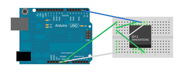
This is how the connections are made:

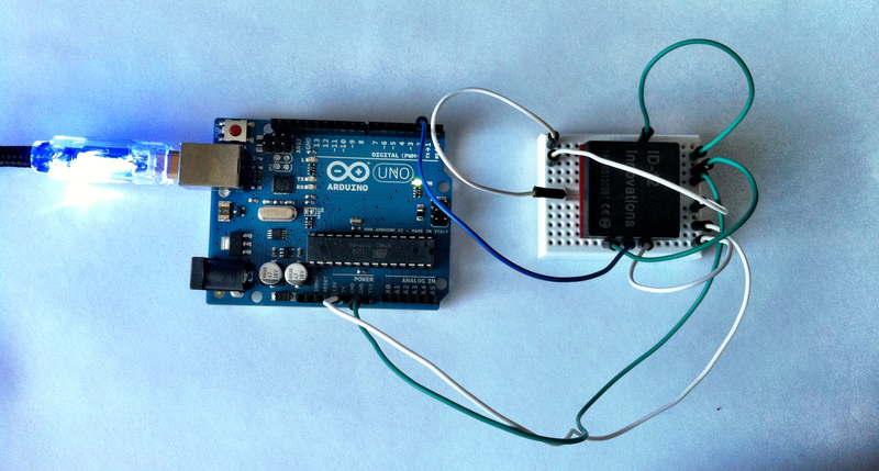
Actually the ID-12 is soldered to a breakout board so this is how everything looks in reality (notice the white wire on the left side of the chip – this is the one that I soldered directly to the chip):

(A big thanks goes out to HC Gilje for the good explaination on how to connect the ID-12 chip.)

Step 2 – coding to get some results

There is some great example code for reading RFID tag data on the Arduino website.

It works quite well, but… the ID-12 chip uses a serial connection and the Arduino just has one serial port (input: pin 0, labeled RX), and internally the flashing and PC connection also uses a serial connection. So you cannot have both connections set up at the same time (therefore it is suggested to disconnect the ID-12 chip when uploading a new software version).

But there is a great solution provided by the Arduino IDE: it comes with a SoftwareSerial library (see “File”, “Examples”, “SoftwareSerial”) which turns two normal pins into a serial port. I guess there are some limitations on this, but for me it works quite well.
If you take a close look at the photo and schematics you’ll see that the blue wire (serial) is connected to pin 2 instead of pin 0. This is because I configured the SoftwareSerial lib to use pins 2 (RX) and 3 (TX) to provide a serial port.

By changing the example code to work with two serial ports and opening a PuTTY on port COM3 I was finally able to see the tag IDs showing up!

On request (please leave a comment below) I’ll share my code – it is currently not proper formatted and commented ;)

What’s next?

I’m very excited that this worked so well, but I’ll continue building upon the code and circuit layout:

  • Putting up the code (actually needs some reformatting and commenting)
  • Reading the data on the PC with a custom application
  • Extending that PC application to provide this data to other applications, maybe using some plugin architecture
  • Getting the ID-12 to work with a FEZ Panda II and a Gadgeteer board

If you have any suggestions, ideas or any other feedback, please feel free to leave a comment below.

Update 14.02.2013

I’ve uploaded the code at http://blog.jcoder.me/files/arduino/RFIDReaderExample.txt

It is based on the example RFID reader code from the Arduino site, except that it uses the software serial connection at described above.

Numeric converter using different bases

Inspired by a short conversation with jsilence I was looking for a NewBase60 converter written in Java and C#.

NewBase60 is a format suitable for building parts of URLs, e.g. for URL shorteners. Instead of just using numbers for the short links it uses letters as well, while internally still using numeric values. (There are different strategies to increase a numeric value: just increase the number, increase it using hexadecmial notation, or using an extended set of characters like NewBase60 does it.)

Sadly, the NewBase60 posting didn’t list a C# implementation, and the link to the Java implementation was broken.

So I decided to write my own version. And while NewBase60 with its given 60 characters is just a special case for such numeric conversions, my Base-N implementation not only includes NewBase60 but also a binary, octal and a hexadecimal converter, a flexible base implementation for user-defined bases/alphabets and a “max. base 36” implementation.

The Base-N code is up on my github page, so feel free to download, use and/or fork it.

If you encounter any bugs or just want to provide any other (positive?) feedback, feel free to leave a comment below.

C# Extension Methods, Part 3

While I’ll probably (have to) focus on Java for the next month, I just came up with the idea of just another extension method class. It is acually not very helpful but it again shows how powerful extension methods can be.

This is how it can be used:

StringBuilder buffer = new StringBuilder();
foreach (int i in 10.To(15))
{
    buffer.AppendLine("" + i);
}

I know that this piece of code does not look very helpful, because the same can easily be done using a simple for loop, but there might be some cases – especially when using LINQ – when it is quite useful to have an iterable range of int values.

The code is up on my github C# extension method project. Feel free to use or fork it.

nHangman – a tiny game engine (prototype)

Inspired by a question on StackOverflow (which was actually about using regex to replace strings used for a Hangman game) I hacked together a file in C# that contains a minimal implementation of the Hangman game.

The code is up on Github: https://github.com/jcoder/nHangman

It’s actually more of a protoype, but maybe it’s helpful to somebody.