Tag Archives: NETMF

Netduino Plus 2 (NETMF) and WS2812 RGB LEDs

Some weeks ago I got some Adafruit NeoPixel, a compact RGB LED module. Each LED module has a WS2812 chip that only needs three wires: power, ground and data. The data protocol is self-clocking, at a rate of 800KHz. The LED modules can be chained to build longer LED stripes. (For more details see the Adafruit NeoPixel Überguide.)

Adafruit provides an Arduino library on github to control the LEDs, but there is no direct support for Microsoft .NET Microframework (NETMF) controllers like the Netduino Plus 2 that I was going to use.

Actually, there is an advanced guide to use NETMF controllers with the WS2812 LEDs, but it requires a custom firmware, because it seems that the GPIO pins of most NETMF controllers are not fast enough to switch the signal at the needed rate (there is a timing needed in the range of 0.4μs to 0.8μs and some websites found out that the GPIO pins have a latency of 17μs). As I nearly bricked a Netduino before, I didn’t want to dive into custom firmwares at this point.

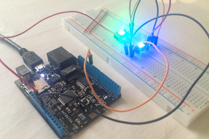
So I found a different way to send the control codes to the LEDs at the needed speed as the following photo proves:

Netduino with WS2812 LEDs

How does it work?

I thought that there must be a faster way to get signals off a Netduino Plus 2 because it has an Ethernet port and SD card slot, and I suppose they need to be adressed faster than 17μs (I haven’t evaluated this, so maybe I’m wrong with that, but it led me in the right direction). Looking at the ports that the Netduino provides my attention was drawn towards the SPI interface.

SPI (Serial Peripheral Interface) is a four-wire master-slave interface for full-duplex communication between chipsets. It has a clock wire (SCLK), output (MOSI) and input (MISO). Normally it can be used at a frequency up to some MHz, so the ports must be really fast.

My assumtion was, that I could only use the output (MOSI) pin, configure the frequency accordingly and send the needed control bytes on that wire to the LEDs. I tried some settings and data packets, but first without any success, but luckily I wasn’t the first one to try this, so I found some code snippets for different microcontrollers, that pointed me into the right direction, e.g. that a timing of 6.666MHz is recommended.

I’ve written two classes and uploaded them to github, so if you have a Netduino Plus 2 (or similar microcontroller) and don’t want to use a custom firmware to control WS2812 RGB LEDs, then maybe you want to give my code a try.

Code on github: https://github.com/jcoder/NetMFNeoPixelSPI

Usage example:

NeoPixelSPI neoPixel = new NeoPixelSPI(Pins.GPIO_PIN_D10, SPI.SPI_module.SPI1);
Pixel pixelRed = new Pixel(255, 0, 0);
Pixel pixelGreen = new Pixel(0, 255, 0);
Pixel pixelBlue = new Pixel(0, 0, 255);
Pixel pixelWhite = new Pixel(255, 255, 255);
Pixel[] block1 = new Pixel[] { pixelRed, pixelWhite };
Pixel[] block2 = new Pixel[] { pixelBlue, pixelGreen };
int waittime = 1000;
while (true)
{
 neoPixel.ShowPixels(block1);
 Thread.Sleep(waittime);
 neoPixel.ShowPixels(block2);
 Thread.Sleep(waittime);
}

The library code is not optimized (yet), and I didn’t write a helper class for easier handling of long LED stripes (because I don’t own one), so feel free to extend the code. I’m not quite sure if this approach is really a good one, but it worked for me.

Also feel free to leave a comment below if you have any remarks, ideas, etc.

As always: use this information and the code on your own risk. ;)

Leaving the FEZ comfort zone – say hello to the breadboard

I’ve been very busy over the last weeks, but now I’ve taken some time to get deeper into the “core electronics part”, which simply means that I got a breadboard and some electronic components like resistors, transistors, LEDs and a lot of wires.

The first step was to get a normal LED on the breadboard blinking by connecting it directly to the Digital IO ports on the FEZ Panda board. Sounds easy but I did not want to break anything so after carefully reading some postings about the topic I connected die Digital IO port to a 220 Ohm resistor which was connected to the LED and then back to Ground. Using the OutputPort class on the given IO port the LED was blinking. That easy :)

As it was not as complicated as I thought it would be, I remembered the 2×24 LCD panel that I got from a friend. I wasn’t sure how it exactly works, but as I found out it has a HD44780 controller on-board that accepts 4-bit commands using additional wires for signals and power. And there is even a very useful C# class at the GHI Electronics website, nearly ready to use.

And guess what? After connecting the wires and including the pre-defined class I got the LCD working! Awesome!

I actually had to de-wire everything to put it back in the boxes for storage, but it’s not as hard as I thought to put everything together, so manybe I’ll use the LCD in some of the next projects.

And the next part of equipment is waiting: I just soldered the needed connectors to a 4×7 segment LED element, so stay tuned ;)

Networking with the FEZ Panda II

First of all: using the ethernet connection with the FEZ Panda II works well if you follow the steps from GHIElectronic’s eBook “FEZ Internet of Things”. You just set up MAC, IP, netmask, gateway and DNS server settings and you are ready to go.

But, there is actually a drawback: although the FEZ Panda II uses the .NET Microframework 4.x (NETMF), it does not fully support the System.Net namespace due to resource limitations of the device!

This means that all code using System.Net from the NETMF will not work, giving you a System.NotSupportedException. One disadvantage of this is, that most 3rd party NETMF projects using networking will not work as well.

The workaround to this problem is to use the network classes provided by GHIElectronics. In detail, it helps to add the following references to your project:

  • GHIElectronics.NETMF.Net
  • GHIElectronics.NETMF.W5100
  • GHIElectronics.NETMF.W5100.Http

Those references provide all the classes used to successfully establish network connections via TCP or UDP. As said above, the examples in the eBook are very useful, so I’ll not go into detail here ;)

Now that I basically got the network connection working I’m going to think about some example usages and over the course of the next weeks I’ll share my observations (and maybe some code too) here.

Netduino Switching Lights (with interaction)

After my first and very simple Netduino project, the traffic lights, I wanted to get a little step further. So I’ve put together some lines of code to make the LEDs show the sequence red, yellow, green, off with a fixed interval in between. And I want this interval to be controllable with the Variable Resistor (POT).

The main goal was actually not to build some great light animation, but to learn more about the possibilities behind the scenes. You’ll find find the complete project in the attached ZIP file (see end of this posting), so I’ll focus on two simple, but helpful details in this posting.

The first one is that I encapsulated the access to the LEDs using a class which holds a reference to the output pin, the LED’s state (on/off) and provides the three methods On(), Off() and Toggle() to make it easier to interact with the LED in code. I’m pretty sure that I’ll use (and extend) this LED class in upcoming projects.

public class LED : IDisposable
{
    private OutputPort port;
    private bool state;

    public LED(FEZ_Pin.Digital pin)
        : this(pin, false)
    {
    }

    public LED(FEZ_Pin.Digital pin, bool initialState)
    {
        this.port = new OutputPort((Cpu.Pin)pin, initialState);
        this.state = initialState;
    }

    public void On()
    {
        this.port.Write(true);
        this.state = true;
    }

    public void Off()
    {
        this.port.Write(false);
        this.state = false;
    }

    public void Toggle()
    {
        if (this.state == true)
        {
            this.Off();
        }
        else
        {
            this.On();
        }
    }

    public bool State
    {
        get
        {
            return this.state;
        }
    }

    public void Dispose()
    {
        this.port.Dispose();
    }

}

The second class simplifies the Analog Input handling. When attaching the POT you normally create a static variable to hold the reference to the analog input and read its value when you think it might have changed and you then need to react to this change.

This might be a practical approach in many cases but sometimes it would be nice to be more event-based. So that’s where the class ActiveAnalog kicks in. It encapsules an analog input pin offers the event ValueChanged which provides the current value and the offset change from the previous value. Internally a thread is used to read the analog pin’s value every 20 milliseconds, compare the value with the previous value and fire the event if the value has changed. Nothing spectacular, but it makes it easier for some projects to react on analog pin value changes.

public class ActiveAnalog : IDisposable
{
    private const int READ_INTERVAL = 20;
    private AnalogIn analogPin;
    private Thread readThread;
    private bool active = true;
    private int previousValue;
    private int currentValue;

    public delegate void AnalogValueChange(int currentValue, int offset);

    public event AnalogValueChange ValueChanged;

    public ActiveAnalog(FEZ_Pin.AnalogIn pin)
        : this(pin, 100)
    {
    }

    public ActiveAnalog(FEZ_Pin.AnalogIn pin, int maxScale)
    {
        if (maxScale < 1)         {             maxScale = 1;         } else if (maxScale > 3300)
        {
            maxScale = 3300;
        }
        this.analogPin = new AnalogIn((AnalogIn.Pin)pin);
        this.analogPin.SetLinearScale(0, maxScale);
        this.readThread = new Thread(this.ReadValue);
        this.readThread.Start();
    }

    private void ReadValue()
    {
        this.currentValue = this.analogPin.Read();
        while (this.active)
        {
            this.previousValue = this.currentValue;
            this.currentValue = this.analogPin.Read();
            if (this.previousValue != this.currentValue)
            {
                if (this.ValueChanged != null)
                {
                    this.ValueChanged(this.currentValue, this.currentValue - this.previousValue);
                }
            }
            try
            {
                Thread.Sleep(READ_INTERVAL);
            }
            catch (Exception)
            {
            }
        }
    }

    public int CurrentValue
    {
        get
        {
            return this.currentValue;
        }
    }

    public int PreviousValue
    {
        get
        {
            return this.previousValue;
        }
    }

    public void Dispose()
    {
        this.active = false;
        this.readThread.Abort();
        this.readThread = null;
    }
}

The complete project is available for download at http://blog.jcoder.me/files/Netduino/NetduinoSwitchingLights.zip