The mission: getting started with RFID
With my recent gadget order I also bought an ID-12 RFID reader with a corresponding breakout board. The breakout board is needed because the ID12 chip contacts have a 2mm grid while the breadboards have a 2.54mm grid.
Step 1 – setting up the circuits
Yesterday I soldered the reader and connectors to the breakout board (not a very easy task for a non-soldering-expert like me), and today I tried to get it working. And guess what: it didn’t work :(
After each step of soldering I checked the connections with a multimeter and everything seems to work fine (except that I got confused, because on the breakout board the pins 3 and 4 both connect to the antenna somehow and are then connected which I did not expect).
But when trying to get some data out of the assembled circuit nothing happened, and after some checks I found the error: the pin 2 did not connect correctly to the pin on the ID-12 chip. I wasn’t expecting this, so I tried to fix the soldering at that connection, but still no success, so finally I had to solder a testing wire to the pin, and then the contact worked.
Conclusion up to this point: check the soldering connections after each step, even if they look good.
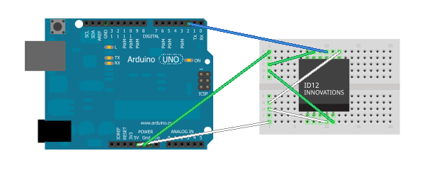
This is how the connections are made:
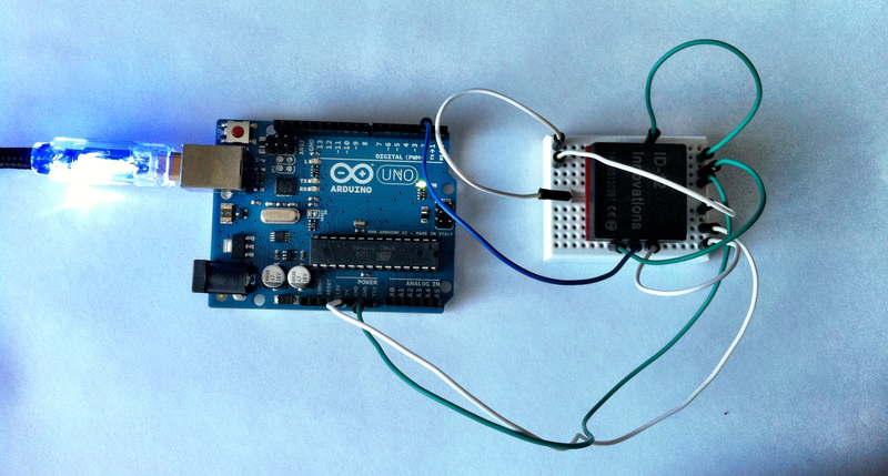
Actually the ID-12 is soldered to a breakout board so this is how everything looks in reality (notice the white wire on the left side of the chip – this is the one that I soldered directly to the chip):
(A big thanks goes out to HC Gilje for the good explaination on how to connect the ID-12 chip.)
Step 2 – coding to get some results
There is some great example code for reading RFID tag data on the Arduino website.
It works quite well, but… the ID-12 chip uses a serial connection and the Arduino just has one serial port (input: pin 0, labeled RX), and internally the flashing and PC connection also uses a serial connection. So you cannot have both connections set up at the same time (therefore it is suggested to disconnect the ID-12 chip when uploading a new software version).
But there is a great solution provided by the Arduino IDE: it comes with a SoftwareSerial library (see “File”, “Examples”, “SoftwareSerial”) which turns two normal pins into a serial port. I guess there are some limitations on this, but for me it works quite well.
If you take a close look at the photo and schematics you’ll see that the blue wire (serial) is connected to pin 2 instead of pin 0. This is because I configured the SoftwareSerial lib to use pins 2 (RX) and 3 (TX) to provide a serial port.
By changing the example code to work with two serial ports and opening a PuTTY on port COM3 I was finally able to see the tag IDs showing up!
On request (please leave a comment below) I’ll share my code – it is currently not proper formatted and commented ;)
What’s next?
I’m very excited that this worked so well, but I’ll continue building upon the code and circuit layout:
Putting up the code (actually needs some reformatting and commenting)- Reading the data on the PC with a custom application
- Extending that PC application to provide this data to other applications, maybe using some plugin architecture
- Getting the ID-12 to work with a FEZ Panda II and a Gadgeteer board
If you have any suggestions, ideas or any other feedback, please feel free to leave a comment below.
Update 14.02.2013
I’ve uploaded the code at http://blog.jcoder.me/files/arduino/RFIDReaderExample.txt
It is based on the example RFID reader code from the Arduino site, except that it uses the software serial connection at described above.


