Category Archives: Arduino

Arduino PWM in slow motion

Although I’m mostly working with the “normal” digital input / output on the Arduino, it might be a good idea to play with the PWM output, too, just to have a basic knowledge about it if needed.

I’ll not go too much into detail about the theoretical background of PWM (highly suggesting you to read the Wikipedia article about PWM if you want to learn more about it). Simply speaking, PWM on the Arduino creates an analogue signal between 0 and 5 Volts by pulsing the power with an interval, e.g. to provide 50% (2.5 Volts) the power is pulsed at a rate of 500 Hz (Arduino uses this frequency for PWM) with half of the time provding either 5 Volts or 0 Volts.

So, what about connecting a LED to the Arduino PWM, powering it at 50% and using high speed video recording?

Arduino PWM in slow motion from Nils on Vimeo.

At 1000 frames per second you can see the flickering that is caused by the switching power on and off at high frequency.

I currently don’t have any use case for PWM in my projects but it’s good to know how it basically works if needed ;)

ATtiny45 meets 74HC595

Earlier today I’ve been following the Arduino Tutorial for driving a 74HC595 shift register which turned out to work pretty well.

In short, a shift register is an electronical component that can be controlled using 3 wires to change the output of 8 pins, or even more when two or more shift registers are chained together. Using a shift register can be useful when you need some more output pins on a microcontroller but only want to use few pins on the microcontroller itself.

I really suggest taking a look at the linked tutorial above for more information, everything worked great following the steps described there.

Limited number of pins on a microcontroller? Did anybody say “ATtiny”?!

Yes, there we go:

It is pretty straight forward to port the Arduino example code for controlling a shift register to work with an ATtiny45 as well.

  • Upload the ArduinoISP sketch to the Arduino Uno
  • Load the Shift Register sketch into the Arduino IDE
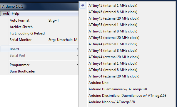
  • Switch the board settings to ATtiny45
  • Connect the ATtiny45 to the Arduino Uno (see my previous posting for more infos)
  • Upload the sketch through the Adruino Uno to the ATtiny

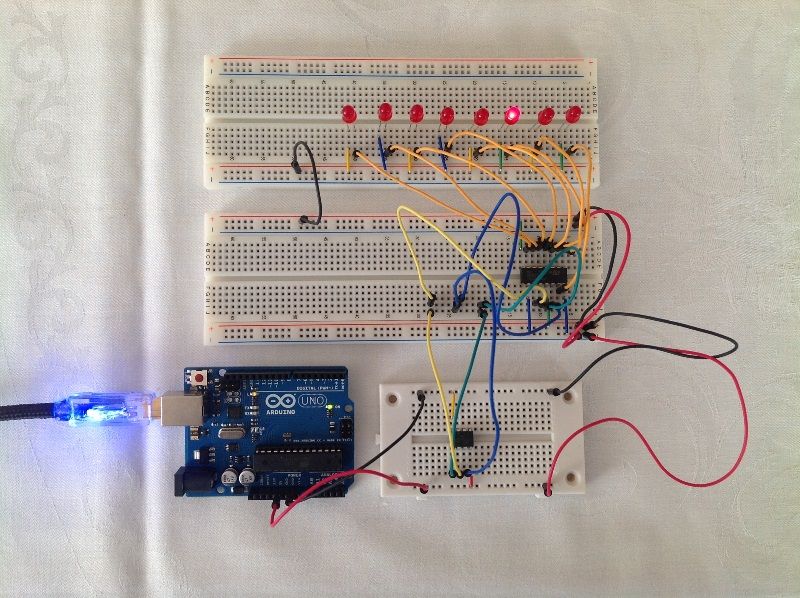
As you can see in the photo above, the Arduino is only used as a power source, the shift register – lighting the LEDs – is just driven by the ATtiny45 on the small breadboard.

I’ve been using a very simple blinking pattern which I set up in the code in an array of bytes (can you guess the pattern? shouldn’t be too hard due to the LED setup), and the program is about 1084 bytes in size. As the ATtiny45 comes with 4096 bytes of program memory there is still a decent amount of space left to build a more complex program, because I guess most of the code is used by the “invisible” part of your program (not the directly written user code but the “infrastructure” code to make it run on the chip) – but that’s just a guess ;)

Anyway, shift registers are a powerful “tool” which is easy to use because the Arduino comes with both predefined functions to work with shift registers and also useful examples, so depending on your project needs you might want to give the shift registers a try.

First steps with the ATtiny 45

The ATMEL ATtiny 45 is an 8-bit programmable microcontroller chip. Some weeks ago I stumbled upon this How-To article by Matt from MAKE about the ATtiny 45 and with my last electronics order I got one (actually two, just in case I accidentially blew one up).

Yesterday I took the time and got it up and running:

Following the tutorial at the MIT Media Lab page it took no longer than 30 minutes to make the microcontroller drive two LEDs.

Although the tutorial was very helpful some things have changed in the current software versions, so (as promised in my last blog posting) this is what I did differently:

1. Copying the ATTiny files

  • doing so as described in the tutorial
  • but: they are showing up as simple devices under “Tools”, “Board”

2. Preparing the Arduino Uno

  • connect the Arduino Uno via USB to the PC
  • start the Arduion IDE 1.0.1
  • open “ArduinoISP” from “File”, “Examples”
  • upload it to the Arduino Uno
  • when finished, connect Arduino Uno to ATtiny on its breadboard, see tutorial for details

3. You(r) program

  • open the blinking example, change pin 0
  • select “Tools”, “Programmer”, “Arduino as ISP”
  • upload program using “File”, “Upload Using Programmer”

4. Done

  • depending on your program and breadboard setup, the LED(s) should be blinking now

What’s next?
I’m not quite sure, but I think the ATtiny 45 is a cool chip, so I’m really looking forward to finding a good way to integrate it into upcoming projects.

Links
ATMEL ATtiny 45 http://www.atmel.com/devices/attiny45.aspx
MAKE article http://blog.makezine.com/2011/10/10/how-to-shrinkify-your-arduino-projects/
MIT Media Lab page ATtiny http://hlt.media.mit.edu/?p=1695
My ATtiny 45 video at YouTube http://youtu.be/Jv3yjzZJJ2c

Reading RFID tags with Arduino and ID12

The mission: getting started with RFID

With my recent gadget order I also bought an ID-12 RFID reader with a corresponding breakout board. The breakout board is needed because the ID12 chip contacts have a 2mm grid while the breadboards have a 2.54mm grid.

Step 1 – setting up the circuits

Yesterday I soldered the reader and connectors to the breakout board (not a very easy task for a non-soldering-expert like me), and today I tried to get it working. And guess what: it didn’t work :(

After each step of soldering I checked the connections with a multimeter and everything seems to work fine (except that I got confused, because on the breakout board the pins 3 and 4 both connect to the antenna somehow and are then connected which I did not expect).

But when trying to get some data out of the assembled circuit nothing happened, and after some checks I found the error: the pin 2 did not connect correctly to the pin on the ID-12 chip. I wasn’t expecting this, so I tried to fix the soldering at that connection, but still no success, so finally I had to solder a testing wire to the pin, and then the contact worked.

Conclusion up to this point: check the soldering connections after each step, even if they look good.

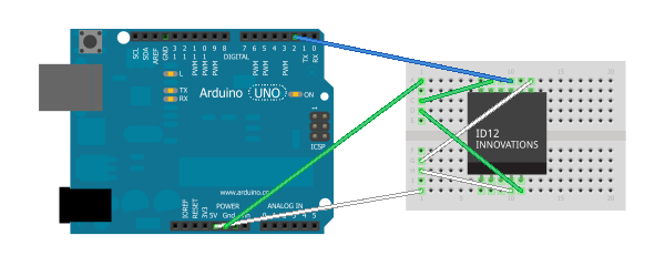
This is how the connections are made:
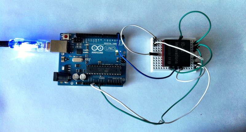
Actually the ID-12 is soldered to a breakout board so this is how everything looks in reality (notice the white wire on the left side of the chip – this is the one that I soldered directly to the chip):
(A big thanks goes out to HC Gilje for the good explaination on how to connect the ID-12 chip.)

Step 2 – coding to get some results

There is some great example code for reading RFID tag data on the Arduino website.

It works quite well, but… the ID-12 chip uses a serial connection and the Arduino just has one serial port (input: pin 0, labeled RX), and internally the flashing and PC connection also uses a serial connection. So you cannot have both connections set up at the same time (therefore it is suggested to disconnect the ID-12 chip when uploading a new software version).

But there is a great solution provided by the Arduino IDE: it comes with a SoftwareSerial library (see “File”, “Examples”, “SoftwareSerial”) which turns two normal pins into a serial port. I guess there are some limitations on this, but for me it works quite well.
If you take a close look at the photo and schematics you’ll see that the blue wire (serial) is connected to pin 2 instead of pin 0. This is because I configured the SoftwareSerial lib to use pins 2 (RX) and 3 (TX) to provide a serial port.

By changing the example code to work with two serial ports and opening a PuTTY on port COM3 I was finally able to see the tag IDs showing up!

On request (please leave a comment below) I’ll share my code – it is currently not proper formatted and commented ;)

What’s next?

I’m very excited that this worked so well, but I’ll continue building upon the code and circuit layout:

  • Putting up the code (actually needs some reformatting and commenting)
  • Reading the data on the PC with a custom application
  • Extending that PC application to provide this data to other applications, maybe using some plugin architecture
  • Getting the ID-12 to work with a FEZ Panda II and a Gadgeteer board

If you have any suggestions, ideas or any other feedback, please feel free to leave a comment below.

Update 14.02.2013

I’ve uploaded the code at http://blog.jcoder.me/files/arduino/RFIDReaderExample.txt

It is based on the example RFID reader code from the Arduino site, except that it uses the software serial connection at described above.

New gadget: Arduino Uno

Just a short update: I recently received some fun stuff, including an Arduino Uno.

I’ve also been soldering some components together, and I’m really excited about getting into the Arduino Universe. So stay tuned for more updates on that topic.

As a first impression I shot a little video with two blinking LEDs (seen on the right side in the video):