Some weeks ago I got some Adafruit NeoPixel, a compact RGB LED module. Each LED module has a WS2812 chip that only needs three wires: power, ground and data. The data protocol is self-clocking, at a rate of 800KHz. The LED modules can be chained to build longer LED stripes. (For more details see the Adafruit NeoPixel Überguide.)
Adafruit provides an Arduino library on github to control the LEDs, but there is no direct support for Microsoft .NET Microframework (NETMF) controllers like the Netduino Plus 2 that I was going to use.
Actually, there is an advanced guide to use NETMF controllers with the WS2812 LEDs, but it requires a custom firmware, because it seems that the GPIO pins of most NETMF controllers are not fast enough to switch the signal at the needed rate (there is a timing needed in the range of 0.4μs to 0.8μs and some websites found out that the GPIO pins have a latency of 17μs). As I nearly bricked a Netduino before, I didn’t want to dive into custom firmwares at this point.
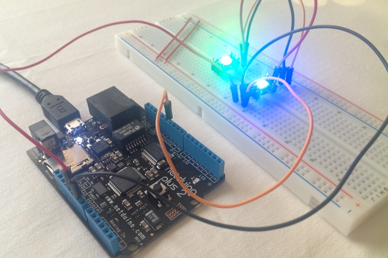
So I found a different way to send the control codes to the LEDs at the needed speed as the following photo proves:
How does it work?
I thought that there must be a faster way to get signals off a Netduino Plus 2 because it has an Ethernet port and SD card slot, and I suppose they need to be adressed faster than 17μs (I haven’t evaluated this, so maybe I’m wrong with that, but it led me in the right direction). Looking at the ports that the Netduino provides my attention was drawn towards the SPI interface.
SPI (Serial Peripheral Interface) is a four-wire master-slave interface for full-duplex communication between chipsets. It has a clock wire (SCLK), output (MOSI) and input (MISO). Normally it can be used at a frequency up to some MHz, so the ports must be really fast.
My assumtion was, that I could only use the output (MOSI) pin, configure the frequency accordingly and send the needed control bytes on that wire to the LEDs. I tried some settings and data packets, but first without any success, but luckily I wasn’t the first one to try this, so I found some code snippets for different microcontrollers, that pointed me into the right direction, e.g. that a timing of 6.666MHz is recommended.
I’ve written two classes and uploaded them to github, so if you have a Netduino Plus 2 (or similar microcontroller) and don’t want to use a custom firmware to control WS2812 RGB LEDs, then maybe you want to give my code a try.
Code on github: https://github.com/jcoder/NetMFNeoPixelSPI
Usage example:
NeoPixelSPI neoPixel = new NeoPixelSPI(Pins.GPIO_PIN_D10, SPI.SPI_module.SPI1);
Pixel pixelRed = new Pixel(255, 0, 0);
Pixel pixelGreen = new Pixel(0, 255, 0);
Pixel pixelBlue = new Pixel(0, 0, 255);
Pixel pixelWhite = new Pixel(255, 255, 255);
Pixel[] block1 = new Pixel[] { pixelRed, pixelWhite };
Pixel[] block2 = new Pixel[] { pixelBlue, pixelGreen };
int waittime = 1000;
while (true)
{
 neoPixel.ShowPixels(block1);
 Thread.Sleep(waittime);
 neoPixel.ShowPixels(block2);
 Thread.Sleep(waittime);
}
The library code is not optimized (yet), and I didn’t write a helper class for easier handling of long LED stripes (because I don’t own one), so feel free to extend the code. I’m not quite sure if this approach is really a good one, but it worked for me.
Also feel free to leave a comment below if you have any remarks, ideas, etc.
As always: use this information and the code on your own risk. ;)


7 responses to “Netduino Plus 2 (NETMF) and WS2812 RGB LEDs”